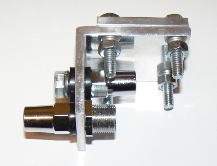
In order to simplify antenna setup in a city park I purchased some Hamstick antennas. I had never used any before and so far they seem to do a nice job. I also bought the “DAKAD” mount that is available at R&L Electronics. I think it is a good buy, but if you really want your Hamsticks to function as a dipole you will need to make two small modifications. The mount will support two Hamsticks in a dipole configuration. Here is a picture of an unmodified mount.
Notice that the back element support is fully insulated and just floats. It is not in the circuit at all. The front element support is mounted as it normally would be for simple vertical antenna use. The left hand side is isolated from the mount and the right hand side is connected to the mount. If the mount is grounded then the shield of the coax is grounded at that point. You can install two Hamsticks to the mount, but you will not have a dipole and the feed impedance will be half that of a dipole, about thirty six ohms.
Last time I was out getting ready to make a few contacts I discovered what is above by double checking with an ohm meter. So I used some electrical tape and wire and made the system into a real dipole mount. After a few contacts I packed it up making plans to make the modifications permanent. I really feel like I lucked out at a small local hardware store. They had the exact size and type washer needed. The one on the left is the new washer.
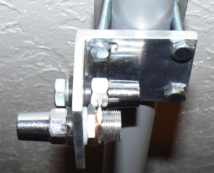 As you can see there is a white washer on the right hand side on the front support. The washer had the same characteristics as the black washers, but just a bit thinner. No matter there as I do not plan on running a full 250 watts with this setup. I also did have to find a nut to screw on to the SO-239 to hold the wire that ties the shield side of the coax to the other element mount.
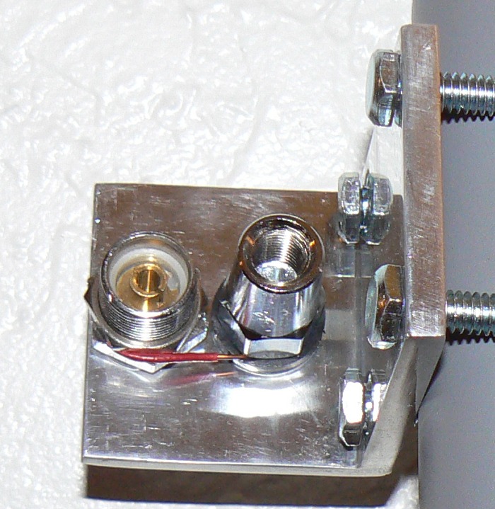 There is a difference in height in the above picture, but the wire works. A solid piece of copper strap could also be placed between the two element supports. So the shield is tied to the element support on the right that was originally just floating with no connections. There is no electrical connection to the mount.
The next step was to fashion a balun. Going from unbalanced coax to a balanced antenna will function, but not as well without the proper match. Feedline radiation is one problem associated with not using a balun. I read that a coaxial air core balun should be made up of eighteen to twenty one feet of coax and was recommended that it be wound on a four inch form or PVC pipe. I had lots of three inch pipe and so that is what I used. What you see below is 20 feet of coax held by wire ties on each end.
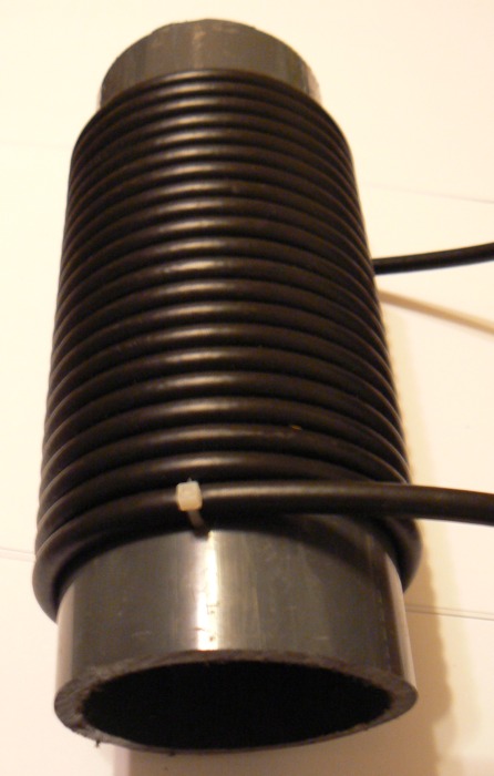 For size perspective remember that this is RG-6 quad shield coax. ($70 for 1k feet.) The center impedance of a dipole is ideally seventy two ohms. RG-6 is seventy five ohms. The Icom 703 handles the “mismatch” if any just fine. Most modern radios are designed to handle fifty to seventy five ohms at the antenna terminal. What most people forget is that a fixed system that operates on only one frequency can be designed by the book and the feed impedance seen by the transmitter can be precisely matched. However for Amateur radio just tuning down the band causes the impedance your transmitter sees to change.
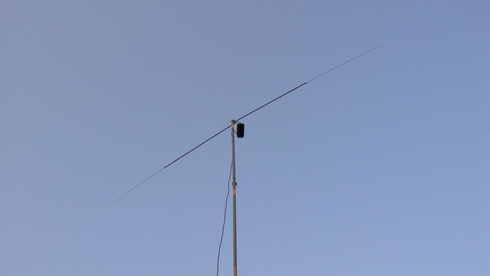 While I heard several foreign stations and their pile-ups I had two short contacts. The operating location was just outside the WØSV St. Cloud Amateur Radio Club’s building. The first was with a station near Augusta, Georgia. We both had about 57 reports with heavy fading. The second contact was with a station in Roanoke, Virginia. I received a 58 report with ten watts from the Icom 703+. Those contacts were on twenty meters. After swapping the elements and seeing what forty meters sounded like and how it measured I packed up as it was almost too dark to see where the coax was on the ground.
Today I received a 1:1 current balun from Balun Designs. It is the same brand balun that I use to match three hundred ohm ladder line to the radio with a 4:1 balun. My goal is to see if there is any difference using an air wound coax balun and a balun with a toroid core. I don’t think I have ever taken the time make that measurement.
[Update]
I like the store bought 1:1 current balun better than the air core baluns although I need to test the air cores again. On forty meters I had to remove the white insulator in order for the antenna to work. I would guess that it has to do with the design and original intent of the antennas although I need to double check that. I think there is an intermittent connection in the system. The MFJ-259b showed 54 ohms at the radio end of the feed line with RG-6 coax. and the commercial 1:1 balun.
Tim

